Tips by Quinn Brockmyre
Definitions:
- CLK: Clock, you all know this one.
- CLR: Clear, same thing.
- PROG: Program, the index for which ROM (program) we want to read commands from in the Inst_mem
- PC: Program Counter, the pointer to the instruction in the PROG (the little component at the bottom that keeps track of where we are in the PROG) Hint: we will be focusing more on this in the near future for j-types and b-types Register File
- WD: Write Data, this is the data that you will be using when writing to any register that we get from the ALUop (for now). Hint: remember that we only want to write to a register when we are executing a command that actually does that!
- WE: Write Engage, its engage, but we will see in Thursdays class that we do not always want to engage even when executing commands, take branching for example.
- RR0/RR1: Read Registers, just rs1 and rs2
- RD0/RD1: Read Data, Reads the data from two selected registers
- ALU: Arithmetic Logical Unit, this thing is what we use for any arithmetic operations, thing R-type or I-type. We use its output as an input for Write data as all of these commands write to a register.
- ALUSrcB: ALU Source B, this is to take into account immediate values, as you will see in the spec we use it when doing commands like addi since they require us to use an immediate not both RD0 and RD1.
- InstDecoder: Instruction Decoder, we input the IW to “decode” which instruction we are executing, with this information we get the exact control output bits (from your spreadsheet) from a ROM. IMPORTANT: We will be adding to this spreadsheet and component A LOT so be ready for that (we will be adding over 16 instructions next project). This is where most people have made mistakes in this lab and the next project. Always make sure you understand what the output bits do (I will go over them next) and that they are correct in your spreadsheet and correctly updated in the ROM
- RFW: Register File write, this is used to tell us whether the instruction is writing to a register or not. If the instruction is not writing to a register this should be 0. If it is 1 when it should be 0 you will get errors.
- ALUop: Look below for definition. In context for the InstDecoder this is just the selector bit for which ALUop we are going to do
- ALUSrcB: Look below for definition. In context for the InstDecoder this is just the selector bit for which immediate value (or register) we are going to use for the ALUop
- PCsel: PC selector, a selector for determining where in the PC you are going. Essentially, if an instruction is changing your location in the program, this shouldn’t be 0 (pc+=4).
- WDsel: Write data selector, a selector bit to determine what you are writing into the selected register (register is determined by rd that goes into the WR input in Reg_file).
- BRop: Branch op (this is my name for it you might have a different one), this is the selector to determine which branch operation we want to select of the 4.
- Store (MST): Again, you might have a different name for this, but this is the selector to determine whether we are doing a store/save command.
- MemSize (MSZ): Memory Size, again, my name for it, this is the selector that determines which kind of store or load instruction we are doing (SD/SW/SB/LD/LW/LB).
- INUM: Instruction Number, used as a bit to display which instruction we are doing in ASCII.
- You do not technically need all of these selectors as there are ways of determining these things based on the IW, however I recommend you use them.
Recommendations:
- __IMPORTANT__: when making the regs_file with tunnels, I would highly recommend going into edit->settings and turning off “automatic renaming of tunnels” at the bottom. It makes copy pasting already tunneled registered a much better experience.
- I would put the conditionals for each instruction in their own components for inst_decoder (essentially don’t have all the comparator gates in the top level but in their own components if that makes more sense)
- This is the equation that I used for converting bin to hex in the spreadsheet. This is mine, you can do it differently but this one worked for me: = “0x” & DEC2HEX(DECIMAL(SUBSTITUTE([YOUR BINARY COLUMN], “0b”, “”), 2))
- If you want to paste into a ROM from a column in excel or sheets, (to my knowledge) you can only do so for the first 4 address bits of space, after that the ROM has multiple columns instead of just 1 and you cannot past a single column into it. What I would do is just paste the first 4 address bits of instructions, and then change the address bit size and manual copy paste each 1 by 1. (This is only really applicable for the next project)
- __IMPORTANT__: First and foremost, I believe I remembered why I used my conversion for google sheets found below. Looking through the manual for these commands Bin2Hex and Bin2Dec can only take up to 10 bits in total, after that it should give you an “#ERROR”. We will have more than 10 bits of selector bits.
General: Changing input/output position
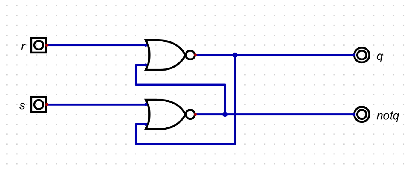
to this:
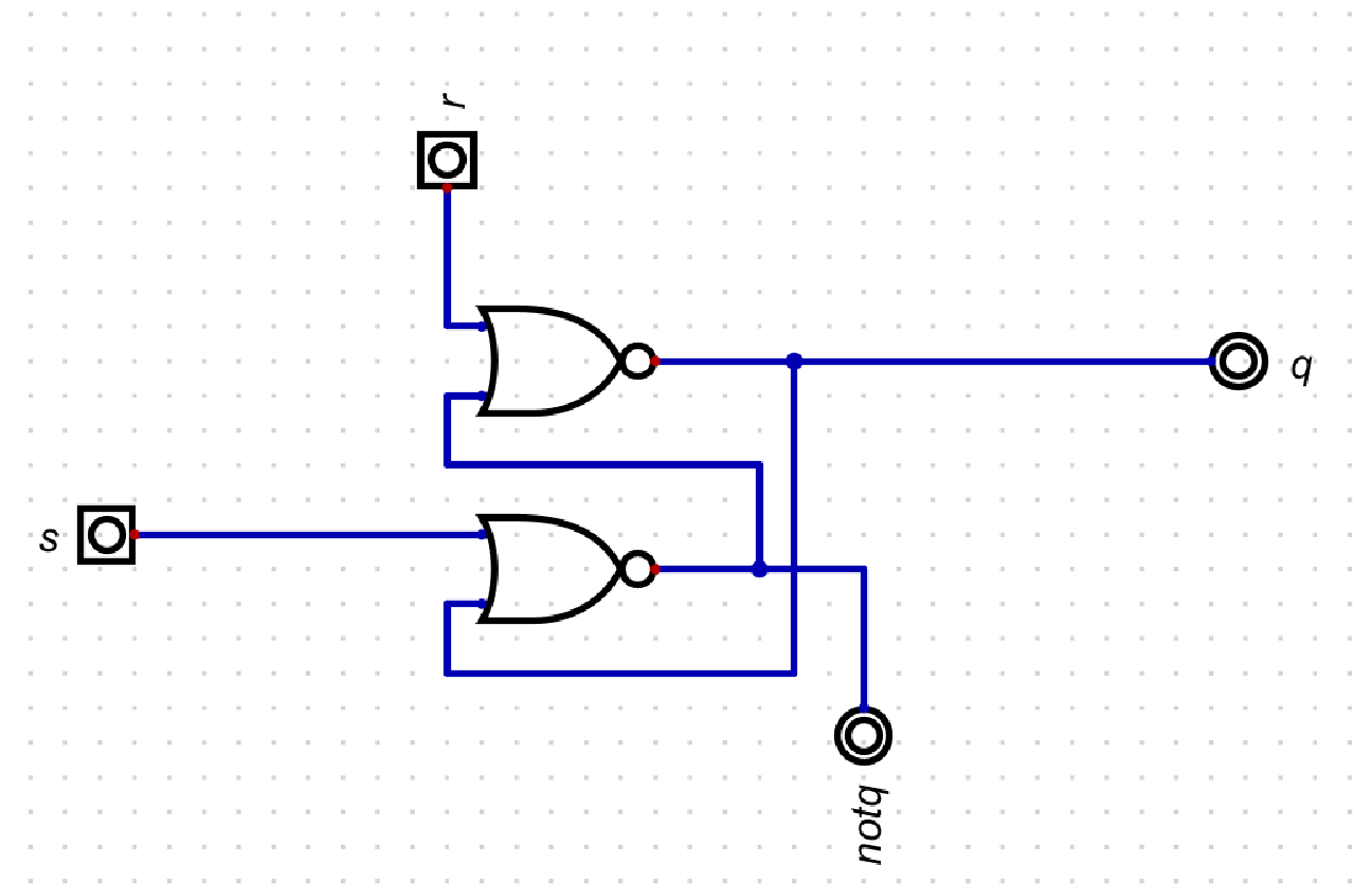
gives us this:
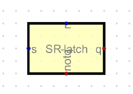
Essentially just rotate the input/output in the circuit using ‘r’ on your keyboard.
For splitting we have 2 possibilities
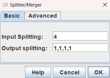
and
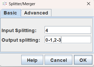
The two differences here is that the second one has to be used when you want to “grab” certain bits from a larger bit number, for example if you want the rd from an IW, you would need bits 7-11. You cannot just type in 5 (as we need those specific 5 bits), you must do 7-11.
Here are some general tips that I wish someone had constantly reminded me of when I did this:
- Always ALWAYS make sure the number you wire to an input has the same amount of bits, when using a constant value like 1 or 0, if it’s being compared to a 32-bit value, it has to be a 32-bit 1 or 0
- Use the test cases from the project06 tests repo. You can open each test case .dig file and copy the test case to your Project06 top-level circuit.
- Debug by running the circuit itself and going through every IW.
- Rewatch the lectures. If you don’t understand something at least try and go through the notes, or watch the lecture that Professor Benson addressed it, one more time, 9 times out of 10 the answer is staring you in the face
- I have said this already, but I recommend using a mouse as it is easier to do the wiring. If you don’t have one ctrl+z (undo) is also really useful if you mess something up, use it!
- Just like the test cases, use probes. Probes do nothing except display the current value that is running through a wire, you can also customize it to display in hex or bin.