Introduction to Digital Design
Schematics due Mon Oct 21st by 11:59pm in your Lab04 GitHub repo
Background
We are now learning the basics of digital logic and digital circuits with the goal of learning enough to build a working computer processor. We will use the Digital application to build and simulate digital circuits: https://github.com/hneemann/Digital. For this lab your are going to build and simulate some simple circuits.
Note that you will be running the Digital application directly on your host OS (e.g., macOS, Windows, or Linux), not on a RISC-V machine or VM. This means that you will need to get the autograder running on your host OS. On Windows, it will be easiest to use WSL Ubuntu, although some students have been able to get it to work in PowerShell. While less convenient, it is possible to run the Digital autograder tests on the BeagleV machines.
Part 1: LEDs
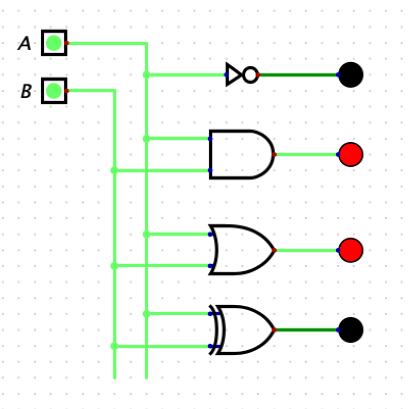
- You will build a circuit in with two inputs and 4 LED output that shows how 4 basics gates work: NOT, AND, OR, and XOR.
- The LED will turn red when the input is high (1) and black when in the input is low (0).
- Here is a screen shot of the circuit you need to build and simulate. Note that you need to add labels to the inputs (A and B):

Part 2: Max2
Consider the C code fragment below:
if (a > b) {
    r = a;
} else {
    r = b;
}
- We will assume that a, b, and r are 2-bit values. That is, the only values a, b, and r can be are 0, 1, 2, or 3.
- Your job is to use sum-of-products to come up with a Boolean algebra equation and a circuit that will compute the max value r (which is also a 2-bit value).
- Your inputs will be
a1,a0,b1,b0and your outputs will ber1andr0. So, you will have two Boolean equations, one forr1and one forr0. - Since there are 4 inputs you will have 2^4 (16) rows in your truth table.
- Submit a working circuit that correctly produces the max value of the two inputs. You do not need to submit the truth table or Boolean algebra equation.
- Your circuit must have input names
a1,a0,b1, andb0. The file must be calledmax2.dig
Part 3: 1-bit full adder
- In lecture, we built a 1-bit half adder (that is, an adder which does not have a carry-in) and showed the Boolean Algebra equation for a 1-bit full adder.
- You will build a 1-bit full adder in Digital, including a carry-in (
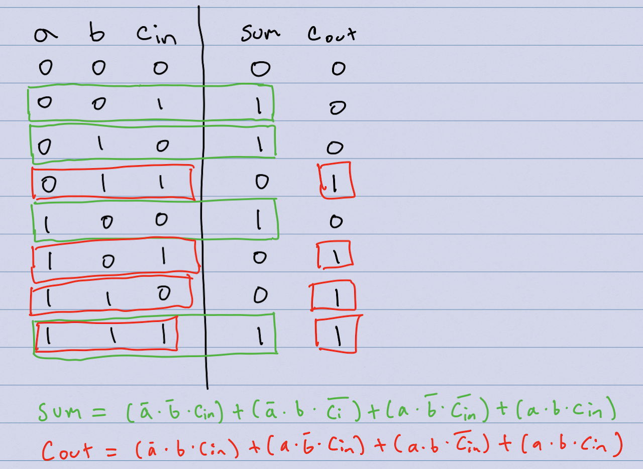
cin) and a carry-out (cout). Your circuit must have inputs nameda,b, andcin, and outputs namedsumandcout. Your file must be named1-bit-full-adder.dig - Here are the truth table and sum-of-products equations for
sumandcout

Part 4: 8-bit Ripple Carry Adder
- You will implement an 8-bit Ripple Carry Adder with two 8-bit inputs, a 1-bit Carry In, one 8-bit result output, and a 1-bit Carry Out.
- Your circuit must have inputs named
a,b, andcin, and outputs namedsumandcout. Your file must be called8-bit-ripple-carry-adder.dig
Rubric
- 33 pts: max2
- 33 pts: 1-bit full adder
- 34 pts: 8-bit full adder
- The LED circuit is just a warmup and will not be graded