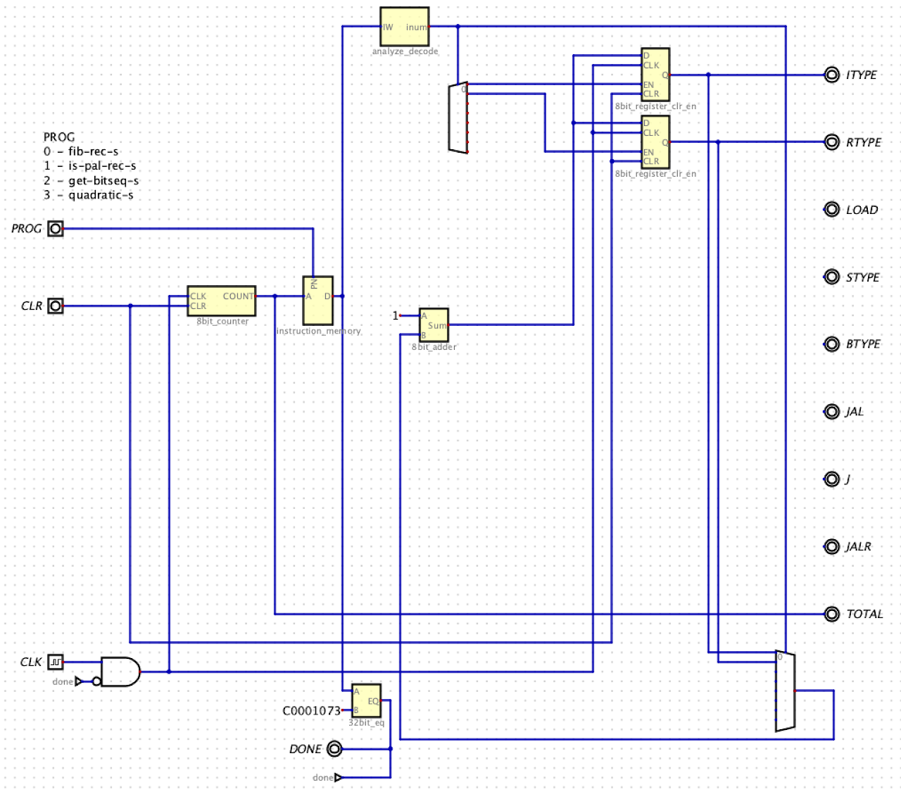
RISC-V Static Analysis Circuit
Circuits due Mon Oct 28th by 11:59pm in your Project05 GitHub Repo
There is no interactive grading for Project05
I will add Exam problems to Project05
Requirements
- Submit your .dig files (one for each circuit) and .hex files to your assignment repo
- You will design and build a circuit which analyzes machine code instructions, i.e. a static analyzer
- Your top-level circuit file must be called
project05.dig- You can choose the names for all other circuit files.
- Your circuit will read machine-language instructions from a ROM component and provide a count of the number of total instructions (
TOTAL) in a program and also count the different instruction types:- I-type opcode (
ITYPE) - R-type opcode (
RTYPE) - Loads (
LOAD) - Stores (
STYPE) - Conditional branches (
BTYPE) - Calls (
JAL) - Unconditional jumps (
J) - Ret (
JALR)
- I-type opcode (
- Your outputs must be named exactly as listed above
- You need these inputs, named as shown:
- A 2-bit input called
PROGthat selects the program to be analyzed - A clock named
CLK - A 1-bit input named
CLRwhich clears the sequential components - To determine the end of a program, your circuit will look for an instruction marker. The marker will be
unimp(0xC0001073). You must add this marker at the end of each program you will analyze. - You only need to support programs that contain up to 256 instructions (including the marker).
- You can use the Digital components: multiplexors, encoders, decoders, gates, splitters, and wires. You must supply all other components yourself including: adders, registers, counters, comparators, instruction storage, and analyzer.
Test input: Your instruction storage will contain the machine code for
fib_rec_s,is_pal_rec_s,get_bitseq_s, andquadratic_sas generated by$ objdump -d file.o | python3 makerom3.py > file_rom.hex- Remember to commit your .hex files in your repo
Given
- Circuits built in lecture
- Screen shot of top-level circuit
Rubric
- Automated Tests (88 pts.)
- Circuit Quality (12 pts.)
Partial Top-level Circuit Image
